$\require{cancel} \newcommand{\Ket}[1]{\left|{#1}\right\rangle} \newcommand{\Bra}[1]{\left\langle{#1}\right|} \newcommand{\Braket}[1]{\left\langle{#1}\right\rangle} \newcommand{\Rsr}[1]{\frac{1}{\sqrt{#1}}} \newcommand{\RSR}[1]{1/\sqrt{#1}} \newcommand{\Verti}{\rvert} \newcommand{\HAT}[1]{\hat{\,#1~}} \DeclareMathOperator{\Tr}{Tr}$
Toffoli Gate
First created in August 2018
A Toffoli gate with flips takes three qubits $\Ket{abc}$ as input and output $\Ket{ab}\otimes\Ket{c\oplus ab}.$
Toffoli is loosely equivalent to the classical AND gate, as the LSD qubit flips when $\Ket a$ and $\Ket b$ are both $\Ket1$.
In order to be reversible, we need to have enough information in the output to regenerate the input state. This is why a Toffoli needs to output three qubits.
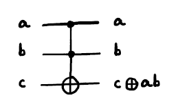
Here is a "Toffoli with flips" (which means $X$). It is also called a CCNOT gate, or $ccX$.
$ccX =\begin{bmatrix} I&0&0&0\\ 0&I&0&0\\ 0&0&I&0\\ 0&0&0&X\\ \end{bmatrix} =\begin{bmatrix} 1&0&0&0&0&0&0&0\\ 0&1&0&0&0&0&0&0\\ 0&0&1&0&0&0&0&0\\ 0&0&0&1&0&0&0&0\\ 0&0&0&0&1&0&0&0\\ 0&0&0&0&0&1&0&0\\ 0&0&0&0&0&0&0&1\\ 0&0&0&0&0&0&1&0\\ \end{bmatrix} .$
$ccX\Ket{abc} =\begin{bmatrix} I&0&0&0\\ 0&I&0&0\\ 0&0&I&0\\ 0&0&0&X\\ \end{bmatrix} \begin{bmatrix} a_0b_0\Ket c\\ a_0b_1\Ket c\\ a_1b_0\Ket c\\ a_1b_1\Ket c\\ \end{bmatrix} =\begin{bmatrix} a_0b_0\Ket c\\ a_0b_1\Ket c\\ a_1b_0\Ket c\\ a_1b_1~X\Ket c\\ \end{bmatrix} .$
General Toffoli
Here is a general Toffoli with operation $U$ instead of $X$:
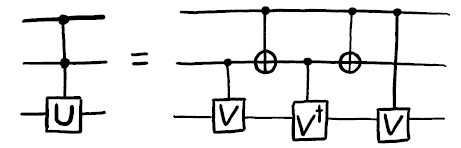
Here $V=\sqrt{U}$ and $V^\dagger=V^{-1}$ (being unitary). From top to bottom on the diagram above, we have
$\Ket a$ does not change
$\Ket b$ is unchanged: either no flips when $\Ket a=\Ket0$, or flipped twice when $\Ket a=\Ket1$.
$\Ket c$ will have
| $a$ | $b$ | Operation | $c$ |
|---|---|---|---|
| 0 | 0 | $I$ | $c$ |
| 0 | 1 | $VV^\dagger=I$ | $c$ |
| 1 | 0 | $V^\dagger V=I$ | $c$ |
| 1 | 1 | $VV=U$ | $Uc$ |
Implement Toffoli
To implement a Toffoli with flips, we need to find $\sqrt X$, which is $HSH$. So $c\sqrt X=H(cS)H$.
Likewise, $\left({\sqrt X}\right)^\dagger=HS^\dagger H.$ So $c\left(\sqrt X\right)^\dagger=H(cS^\dagger)H.$
This is not a "standing offerring" of the IBM Q quantum computer. There is another implementation in IBM Q Experince.
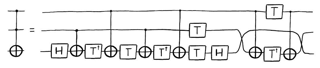

Let us examine the three-qubit system above with $\Ket a$, $\Ket b$ and $\Ket c$, with the last one being the target qubit (acted upon).
| \hspace{0.5em}$\Ket a$\hspace{0.5em} | \hspace{0.5em}$\Ket b$\hspace{0.5em} | \hspace{2em}Operation\hspace{2em} | \hspace{0.5em}Net Op\hspace{0.5em} |
|---|---|---|---|
| $\Ket 0$ | $\Ket 0$ | $HTT^\dagger TT^\dagger H$ | $I$ |
| $\Ket 0$ | $\Ket 1$ | $HTT^\dagger XTT^\dagger XH$ | $I$ |
| $\Ket 1$ | $\Ket 0$ | $HTXT^\dagger TXT^\dagger H$ | $I$ |
| $\Ket 1$ | $\Ket 1$ | $HTXT^\dagger XTXT^\dagger XH$ | $X$ |
For the last row, since $XT^\dagger X=T$, $T^4=Z$, the operation becomes $HZH$, which is $X$.
# Initialisation

import sys
sys.path.append('../')
from qtol import *
# Iteration

# Number of qubits
qbNum = 3

# Define the Quantum and Classical Registers
q = QuantumRegister(qbNum)
c = ClassicalRegister(qbNum)

qc = QuantumCircuit(q, c)

# Preparation
# q2 and q1 are controlling q0
qc.h(q[2])
qc.h(q[1])
qc.iden(q[0])
qc.barrier()

# Circuit building
qc.h(q[0])

qc.cx(q[1], q[0])
qc.tdg(q[0])
qc.cx(q[2], q[0])
qc.t(q[0])

qc.cx(q[1], q[0])
qc.tdg(q[0])
qc.cx(q[2], q[0])
qc.t(q[0])

qc.h(q[0])

# Finalisation
qc.t(q[1])
qc.cx(q[2], q[1])
qc.tdg(q[1])
qc.t(q[2])
qc.cx(q[2], q[1])
# Revelation

#shots = 1024
#decimals = 4

# State Vector
if (True):
    job = execute(qc, backend = 'local_statevector_simulator', shots=shots)
    data = np.round(job.result().get_statevector(qc), decimals)
    print("Raw vector:  ", end=" ")
    print(data)
    vec_norm = np.round(normal_vec(data), decimals)
    print("Normalised:  ", end=" ")
    print(vec_norm)

if (True):
    #vec_text = text_vec(vec_norm, "bra")
    #vec_text = text_vec(vec_norm, "mathbra")
    print("Text form:   ", end=" ")
    vec_text = text_vec(vec_norm)
    print(vec_text)

if (False):
    print("No Plus:     ", end=" ")
    vec_text = no_lplus(vec_text)
    print(vec_text)
    print("No zero dec: ", end=" ")
    vec_text = no_zdec(vec_text)
    print(vec_text)

if (True):
    vec_latex = "\\text{LaTeX form:}\\quad" + no_lplus(text_vec(vec_norm, "latex"))
    print("LaTeX:        " + vec_latex)
    display(Math(vec_latex))
    #display(Math("\\text{This is the truth table of the }ccNOT\\text{ gate.}"))

if (True and qbNum == 1):
    # Block Vector
    bloch = bloch_vector(qc, q, c)
    print("Bloch Vector:", end=" ")
    print(np.round(bloch, decimals))
    #print(bloch_angles(bloch, show="pi"))
    display(Math(bloch_angles(bloch, show="latex", decimals=3)))
    plot_bloch_vector(bloch)

if (True):
    # Histogram
    qc.measure(q, c)
    job = execute(qc, backend = 'local_qasm_simulator', shots=shots)
    data = job.result().get_counts(qc)
    plot_histogram(data)

# Check the circuit (must be not indent or it will not show)
circuit_drawer(qc)

